首页 >> 汽车报警系统,还是“孩子”那些事儿
汽车报警系统,还是“孩子”那些事儿
来源: 时间:2015-11-06
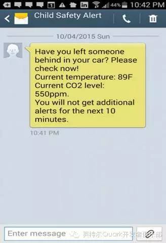
如果你收到这样的短信,千万不要感到莫名其妙,你要做的是赶紧回到你的车上,打开车门。
据不完全统计,每年平均有38个儿童在汽车中窒息而死,原因是被父母锁在车内,里面二氧化碳浓度过高,儿童氧气不够呼吸困难,最后导致悲剧的发生。
#define RLOAD 10.0
/// Calibration resistance at atmospheric CO2 level
#define RZERO 1212.78
/// Parameters for calculating ppm of CO2 from sensor resistance
#define PARA 116.6020682
#define PARB 2.769034857
/// Parameters to model temperature and humidity dependence
#define CORA 0.00035
#define CORB 0.02718
#define CORC 1.39538
#define CORD 0.0018
/// Atmospheric CO2 level for calibration purposes
#define ATMOCO2 400
/// Calibration resistance at atmospheric CO2 level
#define MQ135PIN 0
int redPin = 12; // Red LED connected to digital pin 12
float airthreshold[3] =
{
400, 400, 800
};
void setup()
{
// start the LEDs
pinMode(redPin, OUTPUT); // sets the digital pin as output
//Set up the serial terminal
Serial.begin(9600);
}
void loop()
{
float rzero = getRZero();
float ppm = getPPM();
Serial.print(" CO2: ");
Serial.print(ppm);
Serial.println(" ppm ");
if(ppm > 600)
{
digitalWrite(redPin, HIGH); // sets the Red LED on
}
else
{
digitalWrite(redPin, LOW); // sets the Red LED on
}
Serial.print(" rzero: ");
Serial.println(rzero);
delay(1000);
}
////////////MQ Code///////////////
/**************************************************************************/
/*!
@file MQ135.cpp
@author G.Krocker (Mad Frog Labs)
@license GNU GPLv3
First version of an Arduino Library for the MQ135 gas sensor
TODO: Review the correction factor calculation. This currently relies on
the datasheet but the information there seems to be wrong.
@section HISTORY
v1.0 - First release
*/
/**************************************************************************/
/*!
@brief Get the correction factor to correct for temperature and humidity
@param[in] t The ambient air temperature
@param[in] h The relative humidity
@return The calculated correction factor
*/
/**************************************************************************/
float getCorrectionFactor(float t, float h) {
return CORA * t * t - CORB * t + CORC - (h-33.)*CORD;
}
/**************************************************************************/
/*!
@brief Get the resistance of the sensor, ie. the measurement value
@return The sensor resistance in kOhm
*/
/**************************************************************************/
float getResistance() {
int val = analogRead(MQ135PIN);
return ((1023./(float)val) * 5. - 1.)*RLOAD;
}
/**************************************************************************/
/*!
@brief Get the resistance of the sensor, ie. the measurement value corrected
for temp/hum
@param[in] t The ambient air temperature
@param[in] h The relative humidity
@return The corrected sensor resistance kOhm
*/
/**************************************************************************/
float getCorrectedResistance(float t, float h) {
return getResistance()/getCorrectionFactor(t, h);
}
/**************************************************************************/
/*!
@brief Get the ppm of CO2 sensed (assuming only CO2 in the air)
@return The ppm of CO2 in the air
*/
/**************************************************************************/
float getPPM() {
return PARA * pow((getResistance()/RZERO), -PARB);
}
/**************************************************************************/
/*!
@brief Get the ppm of CO2 sensed (assuming only CO2 in the air), corrected
for temp/hum
@param[in] t The ambient air temperature
@param[in] h The relative humidity
@return The ppm of CO2 in the air
*/
/**************************************************************************/
float getCorrectedPPM(float t, float h) {
return PARA * pow((getCorrectedResistance(t, h)/RZERO), -PARB);
}
/**************************************************************************/
/*!
@brief Get the resistance RZero of the sensor for calibration purposes
@return The sensor resistance RZero in kOhm
*/
/**************************************************************************/
float getRZero() {
return getResistance() * pow((ATMOCO2/PARA), (1./PARB));
}
/**************************************************************************/
/*!
@brief Get the corrected resistance RZero of the sensor for calibration
purposes
@param[in] t The ambient air temperature
@param[in] h The relative humidity
@return The corrected sensor resistance RZero in kOhm
*/
/**************************************************************************/
float getCorrectedRZero(float t, float h) {
return getCorrectedResistance(t, h) * pow((ATMOCO2/PARA), (1./PARB));
}
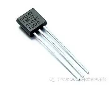
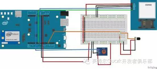
连接器:将DS18B20平坦的一面对向你自己,最左边的是地,中间是信号引脚(引脚13),最右边是+5或+3.3V,4.7k的电阻分别接+5V和信号引脚。
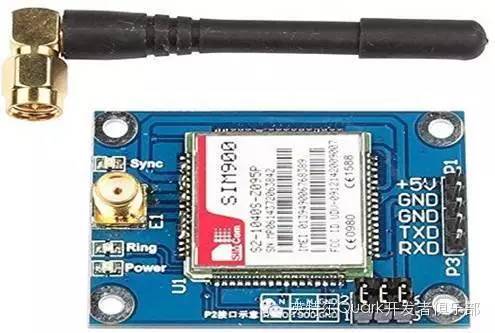
建议将SIM900使用单独的电源上电,连接如下:
RXD与引脚7连接。
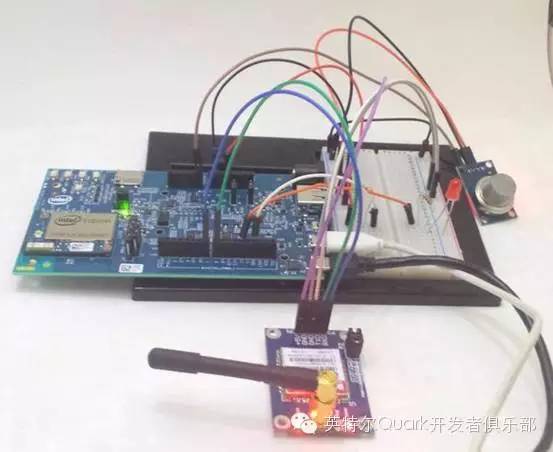
这个想法的目的是提醒你可能忘记了你在车里熟睡的婴儿,毕竟刚为人父母的年轻人,生活了20多年的习惯忽然要改变,忽然要接受生活中多出一个需要去照顾得生命,是需要适应的,这个项目是不是很贴心呢?
推荐文章


